
As global manufacturers pursue cleaner, faster, and more consistent joining methods, Plasmaschweißen is gaining attention in 2026 procurement planning. Its concentrated arc can produce narrow welds, controlled penetration, and stable results on stainless steel, titanium, nickel alloys, and thin sheet. These advantages matter in aerospace components, medical equipment, automotive parts, and energy systems.
Market research supports this direction. The MarketsandMarkets report, Welding Equipment Market—Global Forecast to 2028, identifies automation, digital control, and productivity as major purchasing drivers. The International Federation of Robotics, World Robotics 2024, also reports continued industrial automation growth worldwide. These trends influence plasma welding choices, especially where repeatability and traceable production data are required. However, market forecasts are not shop-floor guarantees. Actual performance depends on material thickness, joint design, shielding gas, operator skill, and maintenance discipline.
This guide examines the leading types for global buyers, including transferred-arc, non-transferred-arc, microplasma, and plasma-MIG or hybrid systems. Each type serves a different operating window. Microplasma can suit delicate sheet and precision assemblies. Transferred-arc systems can deliver deeper penetration for demanding production joints. Hybrid equipment may improve deposition rates, but it can increase setup complexity and training needs.
Standards matter. Buyers should review ISO 3834 quality requirements, ISO 15614-1 procedure qualification, and applicable AWS or regional specifications before approval. A low purchase price can hide higher gas consumption, electrode wear, or integration costs. The best choice is rarely the most powerful machine. It is the system that matches verified production evidence, qualified procedures, and realistic after-sales support.
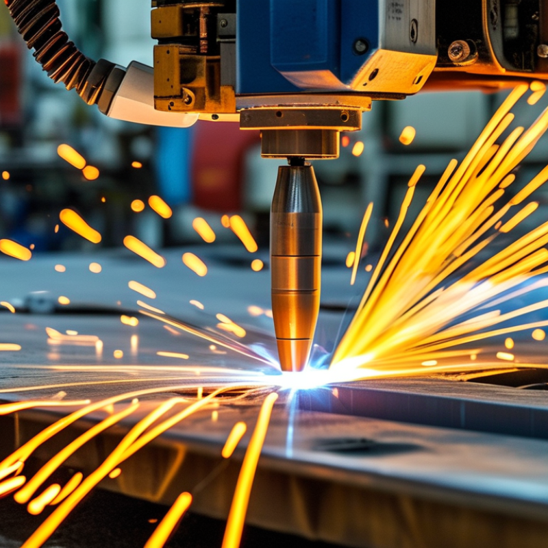
Under ISO 4063, process code 15 means plasma arc welding, not generic arc welding. A constricted arc passes through a fine nozzle, creating a high-temperature plasma jet. The arc normally uses a non-consumable tungsten electrode, plasma gas, and separate shielding gas. This structure gives a narrow fusion zone and strong penetration control. It suits stainless steel, nickel alloys, titanium, and thin precision parts.
The details matter.
ISO 4063 identifies the process, but it does not guarantee weld quality or productivity. A qualified procedure should also define current, gas flow, travel speed, joint design, and inspection criteria. ISO 15614-1 supports procedure qualification, while ISO 9606-1 addresses welder qualification. In practice, I have seen buyers confuse code 15 with TIG welding, listed under code 141. That mistake can distort equipment comparisons and tender documents.
Workforce data also supports careful specification. The U.S. Bureau of Labor Statistics projects about 42,600 annual openings for welders, cutters, solderers, and brazers during 2023–2033. Labor pressure may increase interest in mechanized plasma systems. Still, automation is not a complete answer. Torch alignment, nozzle wear, and shielding turbulence can quickly damage a precise seam. The data is useful, but imperfect. Purchase decisions should connect ISO process identification with tested procedures, operator competence, and documented inspection results.
Compare Microplasma (0.1–15 A), Melt-In (15–100 A), and Keyhole (>100 A)
suits foils, miniature tubing, and delicate stainless parts. Its concentrated arc can hold a narrow bead while limiting distortion. Operators still need clean edges and stable shielding gas. At the low end, setup becomes unforgiving. A tiny change in torch distance may alter arc stability.
uses a conduction-mode arc for sheet, tube, and moderate wall thickness. It creates a visible molten pool without the deep vapor cavity associated with keyhole work. This range is often easier to qualify for repeatable production. Joint fit-up remains important. I would not treat 15 A or 100 A as absolute boundaries; torch design, alloy, speed, and gas change the result.
delivers deep penetration through a narrow opening, making it useful for thicker sections and single-pass joints. The process demands precise travel speed, standoff, gas flow, and backing conditions. Poor alignment can cause undercut, porosity, or an unstable keyhole. Buyers should request test coupons using their actual alloy and thickness, then review cross-sections, hardness, appearance, and repeatability. Do not rely on amperage alone. That shortcut often looks efficient, but it can become expensive.
A plasma arc can approach 28,000°C, according to technical guidance from the Welding Institute. Gas selection determines how efficiently that heat reaches the joint. Argon creates a stable, controllable arc for stainless steel and nickel alloys. Small changes matter. Helium increases arc energy and penetration, but often demands higher flow and tighter control. Hydrogen blends can improve heat transfer, although excessive hydrogen may increase porosity or cracking risks in sensitive materials.
Plasma gas and shielding gas perform different jobs. The plasma gas forms the arc column, while the shielding gas protects molten metal from atmospheric contamination. ISO 14175 classifies shielding gases by composition and welding application. NIST thermophysical data also shows why helium behaves differently from argon at elevated temperatures. Nozzle design then controls arc constriction. A smaller orifice can produce a sharper arc, but it reduces tolerance to misalignment and contamination. A wider nozzle offers more stability, with less concentrated heating. That compromise is easy to underestimate.
For global purchasing, compare gas purity, flow range, electrode compatibility, and nozzle life. ISO 6848 terminology helps standardize plasma welding and cutting specifications across suppliers.
I would not trust a catalog chart alone. Actual results depend on torch stand-off, current, joint gap, and operator adjustment. In production trials, a clean nozzle and a consistent 1–2 mm stand-off can matter more than a theoretical temperature rating. Expect imperfect first trials. Record them carefully.
2026 Top Plasma Welding Types for Global Buyers
Plasma welding includes transferred-arc, non-transferred-arc, microplasma, and keyhole processes. Each type needs documented control of current, arc length, shielding gas, travel speed, and torch alignment. The International Federation of Robotics reported 541,302 industrial robot installations worldwide in 2023. That growth increases demand for repeatable welding procedures, but automation cannot replace qualification evidence.
ISO 15614-1 is used to qualify the welding procedure through representative test coupons. Record joint design, base material, filler metal, plasma parameters, shielding gases, and inspection results. A stable weld bead is not enough. I have seen small gas-flow changes produce porosity near the root. That detail can invalidate confidence in production settings. Procedure qualification records should also reflect the actual thickness range and welding position.
ISO 9606-1 qualifies the welder for applicable fusion-welding variables, while AWS D17.1 addresses aerospace fusion-welding quality and acceptance requirements. These standards serve different purposes. Do not treat one certificate as universal coverage. Check the contract edition, material group, essential variables, visual inspection, and required nondestructive testing. The American Welding Society’s aerospace standard is especially relevant when traceability, cleanliness, and defect limits are tightly controlled. A practical audit should connect the qualified procedure, the trained operator, calibrated equipment, and each production batch. Some purchasing teams still overlook calibration intervals. That is a costly weakness.
| Plasma Welding Type | Typical Operating Range | Common Material Applications | Typical Thickness or Joint Range | Key Process Characteristics | Typical Shielding and Plasma Gases | Primary Buyer Considerations | Procedure and Personnel Verification |
|---|---|---|---|---|---|---|---|
| Micro-Plasma Welding | Approximately 0.1–20 A; finely controlled arc and low heat input | Stainless steel, nickel alloys, titanium, cobalt alloys, and other thin conductive metals | Approximately 0.05–1.5 mm, depending on joint design, material, and equipment | Highly stable constricted arc; suitable for precision tack welding, edge joints, butt joints, and small components | High-purity argon is commonly used for the plasma and shielding streams; gas purity and flow must be qualified | Check low-current stability, torch access, heat-affected-zone control, pulse capability, and repeatability on thin sections | Use a qualified welding procedure specification supported by ISO 15614-1 where applicable; qualify personnel to ISO 9606-1 for steel applications or AWS D17.1 when the work falls within aerospace fusion-welding requirements |
| Melt-In Plasma Welding | Approximately 20–100 A; lower penetration than keyhole mode | Stainless steel, carbon steel, low-alloy steel, nickel alloys, copper alloys, and titanium with suitable procedure controls | Approximately 0.5–3 mm in a single pass, subject to material and joint preparation | Controlled fusion with a visible molten pool; can be used with or without filler metal for thin-sheet fabrication | Argon is commonly used as plasma gas; argon or argon-based mixtures may be used for shielding according to the qualified procedure | Evaluate bead profile, distortion, travel-speed control, filler-metal feeding, and compatibility with mechanized or robotic production | Record essential variables, joint configuration, consumables, gas parameters, current, travel speed, and interpass controls in the procedure qualification record |
| Keyhole Plasma Welding | Typically above 80 A; exact current depends on material, thickness, torch, and travel speed | Stainless steel, carbon and low-alloy steels, nickel alloys, titanium, and selected aluminum or copper applications with specialized control | Approximately 2–10 mm in a single pass for suitable joint designs; actual capability requires procedure testing | High-energy constricted arc creates a keyhole through the joint, allowing deep penetration and potentially reduced filler-metal use | Plasma and shielding gases are normally based on argon; gas composition and flow must be selected according to the material and qualified WPS | Verify keyhole stability, root protection, fit-up tolerance, travel-speed window, backing requirements, and sensitivity to parameter variation | ISO 15614-1 procedure qualification should demonstrate penetration, geometry, mechanical properties, and relevant imperfections; AWS D17.1 may apply to aerospace components |
| Plasma Arc Welding with Filler Metal | Usually approximately 20–200 A, depending on the base material and joint size | Stainless steel, nickel alloys, titanium, carbon steel, low-alloy steel, and selected non-ferrous alloys | Thin to medium sections; commonly used where joint gap, reinforcement, or alloy-specific weld-metal chemistry requires filler | Provides controlled penetration while allowing weld-metal composition and joint volume to be managed through wire or rod addition | Argon or qualified argon-based gas mixtures are commonly used; titanium and reactive alloys require stringent shielding and post-flow control | Confirm filler classification, diameter, surface condition, feeding consistency, wire angle, preheat, interpass temperature, and traceability | Procedure qualification should identify filler classification, size, deposition technique, heat input, and acceptance criteria; welder qualification must match the applicable material and process scope |
| Plasma Arc Welding without Filler | Approximately 0.1–150 A, depending on micro-plasma, melt-in, or keyhole operation | Stainless steel, titanium, nickel alloys, and other materials where autogenous welding is technically suitable | Thin sheet, tubing, foil, and closely fitted butt or lap joints; joint fit-up is especially important | Autogenous fusion reduces consumable handling and can produce a clean weld when edges are accurately prepared and aligned | High-purity argon is frequently used; reactive materials require effective torch shielding, root shielding, and adequate gas coverage | Check edge preparation, gap control, alignment, contamination prevention, root protection, and the risk of burn-through or lack of fusion | Qualify the exact joint and thickness range under ISO 15614-1 or the governing customer specification; visual inspection alone may not demonstrate internal quality |
| Pulsed Plasma Welding | Peak and background current are alternated; frequency and duty cycle are selected for the application | Thin stainless steel, titanium, nickel alloys, precision assemblies, and heat-sensitive components | Approximately 0.1–3 mm in many precision applications, subject to pulse settings and joint design | Pulse control can reduce average heat input, improve pool control, and help manage distortion and penetration on thin material | Argon-based plasma and shielding arrangements are common; gas flow must remain stable during current transitions | Request documented pulse parameters, waveform repeatability, arc-start performance, data logging, and validation at minimum and maximum production conditions | Pulse frequency, peak current, background current, duty cycle, and travel speed may be essential variables; include them in the qualified procedure where required |
| Mechanized or Robotic Plasma Welding | Current and travel speed are selected according to the welding mode; commonly used from low-current precision work to higher-current production welding | Stainless steel, carbon and low-alloy steels, nickel alloys, titanium, and repeatable industrial assemblies | Thin to medium sections with consistent fit-up and controlled joint access | Improves repeatability through programmed travel speed, torch height, current, gas flow, oscillation, and sequence control | Argon or qualified argon-based mixtures; gas monitoring and interlocks are recommended for critical work | Evaluate fixture accuracy, seam tracking, torch alignment, calibration, data recording, maintenance, operator training, and recovery from interruptions | Automation does not replace qualification: validate the welding procedure, qualify the responsible welders or operators as required, and apply AWS D17.1 for relevant aerospace work |
| Standards verification note: ISO 15614-1 is used for the qualification of welding procedures for fusion welding of metallic materials. ISO 9606-1 covers qualification testing of welders for fusion welding of steels; other material groups may require a different applicable qualification standard. AWS D17.1 is an aerospace fusion-welding specification and should be applied when required by the contract, drawing, regulatory framework, or customer quality system. Final acceptance criteria, inspection methods, qualification ranges, and essential variables must always be confirmed against the applicable edition and project specification. | |||||||
Material thickness should guide the power source before convenience features. For sheets from 0.5 to 3 millimeters, choose a stable low-current system with precise arc control. Thin stainless steel can distort quickly. A narrow plasma arc and controlled gas flow help reduce heat input. For thicker sections, higher current capacity and keyhole welding capability become more important. Check the manufacturer’s qualified thickness range, not only the maximum number in a catalog.
Duty cycle shows how long the machine can weld before cooling. A system rated at 60% duty cycle may weld for six minutes within a ten-minute period at its stated current. That rating can change with temperature, ventilation, and output level. In a warm workshop, real performance may be lower. I have seen buyers select impressive peak amperage, then face frequent thermal pauses during long seams. That choice needs reconsideration.
Current range should match the production process, not just occasional repairs. Low-current stability matters for thin titanium, stainless steel, and precision components. Higher ranges support deeper penetration on heavier parts. A broad range is useful, but only when control remains smooth across it. Review torch cooling, gas compatibility, consumable availability, and local electrical standards. Request test welds using your actual thickness and joint design. Numbers alone can mislead.
: Code 15 identifies plasma arc welding. It uses a constricted arc through a fine nozzle.
A tungsten electrode creates the arc. Plasma gas forms the jet, while separate shielding gas protects the weld.
It suits stainless steel, nickel alloys, titanium, and thin precision components. Thin metal can distort quickly.
No. Plasma arc welding uses code 15, while TIG welding uses code 141. Confusing them can affect equipment comparisons.
No. It identifies the process only. Quality also depends on current, gas flow, travel speed, joint design, and inspection.
Test representative coupons under a documented procedure. Record materials, thickness, filler metal, gases, parameters, and inspection results.
Procedure qualification verifies the welding method. Welder qualification verifies operator capability for specified variables. One certificate does not cover everything.
Match current range and duty cycle to actual thickness and production length. Request test welds using the real joint design.
It may allow six welding minutes during a ten-minute period at rated output. Heat, ventilation, and current can reduce real performance.
Check torch alignment, nozzle wear, gas turbulence, cooling, calibration, and consumable supply. Peak amperage alone can mislead.
Plasmaschweißen is a precise arc-welding process classified under ISO 4063 process code 15, using a constricted plasma arc to deliver concentrated heat for stable, high-quality joints. This guide compares microplasma welding at 0.1–15 A, melt-in welding at 15–100 A, and keyhole welding above 100 A, helping buyers match process selection to material thickness, joint design, and penetration requirements.
It also explains how plasma gas, shielding gas, and nozzle design influence an arc that can reach approximately 28,000°C. For reliable production, welding procedures should be qualified in line with ISO 15614-1, welder competence verified under ISO 9606-1, and aerospace-related applications considered against AWS D17.1 where applicable. When selecting 2026 equipment, global buyers should evaluate current range, duty cycle, automation compatibility, serviceability, and material-specific performance rather than relying on nominal power alone.
