
What Are the 2026 Top Laser Cladding Process Types?

Time:2026-10-19 Author:Isabella
0%

Laser cladding is moving from a niche repair technique toward a strategic manufacturing process. The Wohlers Report 2024 valued the global additive manufacturing industry at approximately $20.0 billion in 2023. Its growth reflects stronger demand for material efficiency, part repair, and digitally controlled production. Laser Cladding Process technology fits these needs by placing protective or structural material onto selected surfaces. The result can be a restored turbine blade, a reinforced mining tooth, or a wear-resistant pump seal.

By 2026, the leading process types will likely include powder-fed laser cladding, wire-fed laser cladding, and laser-based directed energy deposition. Powder-fed systems offer precise deposition and flexible alloy selection. Wire-fed systems can improve material utilization and support larger components. Hybrid machines combine laser deposition with CNC machining, reducing handling between build and finishing operations. High-speed laser cladding may also gain attention for thin protective layers and shorter cycle times.

The direction is clear. The ranking is not.

MarketsandMarkets and Grand View Research both report strong growth across laser processing, metal additive manufacturing, and surface engineering. However, their market boundaries and forecasting methods differ. Engineers should not treat one forecast as certainty. Real performance depends on powder quality, wire geometry, laser power, shielding gas, and operator control. A shiny coating is not enough. Cross-sections, hardness tests, dilution measurements, and wear trials still matter. This article examines the top Laser Cladding Process types for 2026, comparing their deposition behavior, industrial fit, cost pressures, and practical limitations. Mistakes remain possible, especially when laboratory results meet uneven production surfaces.
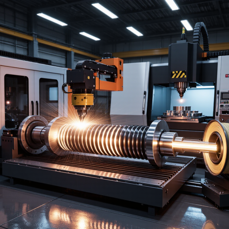
What Are the 2026 Top Laser Cladding Process Types?

Powder-Feed Laser Cladding: 50–90% Powder Utilization and Fine Layers

What Are the 2026 Top Laser Cladding Process Types?

Powder-feed laser cladding remains a practical choice for repairing shafts, valves, and turbine components. It typically achieves 50–90% powder utilization, depending on nozzle design, feed rate, stand-off distance, and melt-pool control. Fine layers can also reduce post-machining, especially on curved surfaces. However, the upper end of that range is not automatic. Poor alignment can leave powder on the worktable instead of the substrate.

The 2024 Wohlers Report places directed energy deposition among established metal additive manufacturing categories. Industry analyses also identify repair, remanufacturing, and surface enhancement as major laser cladding applications. These findings match workshop experience: powder-feed systems offer flexible material changes and localized deposition. Layer thickness often ranges from about 0.2 to 2 millimeters, although material and process settings change the result. Smaller layers improve detail. They also increase production time.

Tips: Begin with a small parameter matrix. Record laser power, travel speed, powder flow, and track overlap. Inspect dilution and porosity through cross-sections, not appearance alone. ISO/ASTM 52900 terminology helps teams describe directed energy deposition consistently. A useful caution is simple: utilization data needs context. It may describe powder entering the melt pool, not powder purchased or loaded into the feeder. That distinction can alter the real production cost.

Wire-Feed Laser Cladding: 1–10 kg/h Deposition for Large Components

What Are the 2026 Top Laser Cladding Process Types?

Wire-Feed Laser Cladding: 1–10 kg/h Deposition for Large Components

Wire-feed laser cladding is becoming a practical choice for large shafts, rollers, valves, and structural parts. It feeds metallic wire into a focused laser melt pool. Deposition rates can range from 1 to 10 kg/h, depending on wire diameter, laser power, travel speed, and alloy type. The process usually offers high material efficiency and lower waste than powder-based methods. It also creates a strong metallurgical bond with controlled dilution.

In production, stable results require more than high deposition speed. Operators must control wire angle, shielding gas, interpass temperature, and surface preparation. A rough surface or inconsistent stand-off distance can produce pores, uneven tracks, or excessive buildup. Real workshop trials often reveal weak edges and distorted profiles. That lesson is easy to overlook. Process engineers should inspect cross-sections, measure hardness, and verify dimensional accuracy before scaling production. Automated monitoring helps, but it does not replace skilled judgment.

Tips: Begin with conservative power and wire-feed settings. Use short test tracks on similar base material. Record melt-pool behavior, layer height, and heat input. For large components, plan the scan path carefully to reduce thermal distortion. A 10 kg/h target may look impressive, yet a slower rate can deliver better geometry and fewer repairs. The best setting is rarely the fastest one.

Pre-Placed Powder Cladding: 0.1–2 mm Layers with Controlled Coverage

Pre-placed powder cladding is a practical laser cladding process for repairing surfaces and adding wear-resistant layers. Operators spread powder directly across the target area before laser exposure. The beam then melts the powder and a thin portion of the substrate, creating a metallurgical bond. Typical layer thickness ranges from 0.1 to 2 mm, depending on powder size, laser power, scanning speed, and coverage requirements.

Controlled coverage is its main advantage. A measured powder bed can follow grooves, edges, or selected repair zones with less material waste. In workshop trials, careful surface preparation often matters more than expected. Oil, oxidation, and uneven powder placement can cause pores, weak bonding, or inconsistent thickness. Layer overlap also needs attention. Excessive overlap may create ridges, while insufficient overlap can leave exposed areas. The process looks simple, but it is not always forgiving.

Tips: Clean and roughen the substrate before powder placement. Check powder height with a simple gauge. Use test tracks to confirm melt depth and dilution. Record laser settings for every material batch. Inspect the finished layer visually and through suitable hardness or bonding tests. A useful reminder: the 2 mm limit is not automatically better. Thicker layers may require multiple passes, greater heat control, and more finishing work. Small adjustments often produce more reliable results than aggressive settings.

High-Speed Laser Cladding: 10–100 m/min Scanning for Thin Coatings

High-speed laser cladding is becoming a practical process type for thin protective coatings in 2026. It uses scanning speeds from 10 to 100 m/min, depending on powder delivery, laser power, coating thickness, and substrate condition. The small melt pool limits heat input and reduces distortion. It can also shorten production cycles for shafts, sheets, and precision components.

A stable process needs more than high scanning speed. Powder flow must remain uniform, while the laser spot, overlap rate, and focal position require close control. In production trials, thin layers often perform well when dilution stays low and bonding remains continuous. Surface preparation is equally important. Oil, oxide, and uneven roughness can create pores or weak zones. The coating may look smooth but still fail under wear.

In-process monitoring helps detect temperature changes, powder interruptions, and unstable melt-pool behavior. A cross-section test should confirm thickness, hardness, porosity, and adhesion. Ten to 100 m/min sounds impressive, but speed alone proves little. Excessive speed can cause incomplete melting or discontinuous tracks. This is not a perfect shortcut. Operators may need to adjust energy density for every alloy and geometry. Even a small change in powder size can alter the final surface.

What Are the 2026 Top Laser Cladding Process Types? – High-Speed Laser Cladding: 10–100 m/min Scanning for Thin Coatings
Process Type Feedstock Typical Laser Power Typical Scanning or Travel Speed Typical Coating Thickness per Layer Deposition Efficiency Heat Input and HAZ Typical Uses and Process Characteristics
High-Speed Laser Cladding Fine metallic powder, commonly approximately 15–63 μm 0.8–6 kW 10–100 m/min Approximately 0.05–0.30 mm Approximately 60–90% powder utilization, depending on nozzle and process setup Very low heat input; narrow heat-affected zone and limited substrate dilution Thin wear- and corrosion-resistant coatings on shafts, hydraulic components, sealing surfaces and precision parts. Designed for high productivity with minimal post-machining.
Conventional Powder-Fed Laser Cladding Metallic powder, commonly approximately 45–150 μm 1–10 kW Approximately 0.2–2.0 m/min Approximately 0.3–2.0 mm Approximately 50–85% powder utilization Low to moderate heat input; dilution is commonly controlled within approximately 2–10% Repair, dimensional restoration and wear protection for molds, tooling, mining parts, valves and large industrial components. Suitable for multilayer builds.
Wire-Fed Laser Cladding Metal wire, commonly approximately 0.4–1.6 mm in diameter 2–12 kW Approximately 0.2–2.0 m/min Approximately 0.5–3.0 mm Typically above 85% wire utilization Low to moderate heat input; generally low material waste and controlled dilution Large-area coating, repair and near-net-shape deposition. Offers clean material handling and high feedstock utilization, but requires accurate wire alignment and melt-pool control.
Coaxial Powder Laser Metal Deposition Metallic powder, commonly approximately 45–150 μm 1–10 kW Approximately 0.3–1.5 m/min Approximately 0.5–2.5 mm Approximately 50–80% powder utilization Low to moderate heat input with good control of dilution and track overlap Multi-axis repair and additive manufacturing. The powder stream is delivered around the laser axis, allowing deposition in different build directions.
Lateral Powder-Fed Laser Cladding Metallic powder, commonly approximately 45–150 μm 1–8 kW Approximately 0.2–1.5 m/min Approximately 0.4–2.0 mm Approximately 45–80% powder utilization Low to moderate heat input; process geometry is sensitive to travel direction and powder-stream alignment Repair and coating of accessible surfaces, including flat, cylindrical and localized areas. The side-delivered powder head is comparatively simple and widely adaptable.
Laser Alloying Preplaced powder, paste, foil or surface-applied alloying material 0.5–8 kW Approximately 0.1–2.0 m/min Approximately 0.1–1.0 mm modified layer Not normally expressed as powder deposition efficiency Moderate heat input; substrate material is intentionally mixed with the added alloying element Surface modification where a metallurgically bonded alloyed layer is required. It can improve hardness, wear resistance or corrosion resistance but normally produces more substrate dilution than thin high-speed cladding.
Laser Surface Remelting No separate feedstock; the substrate or existing coating is remelted 0.5–10 kW Approximately 0.1–5.0 m/min Approximately 0.05–1.0 mm remelted depth Not applicable Localized melting with rapid solidification; normally a shallow heat-affected zone Refines surface microstructure, seals porosity and homogenizes an existing layer. It does not add significant material and therefore is not a standalone coating-deposition method.
Laser Cladding with In-Process Monitoring Powder or wire, selected according to the base process Typically 1–12 kW Approximately 0.2–2.0 m/min; high-speed variants can reach 10–100 m/min Approximately 0.05–3.0 mm, depending on the deposition mode Comparable to the selected powder- or wire-fed process Closed-loop monitoring can stabilize melt-pool temperature, width and height, reducing overheating and geometric variation Used when repeatability and traceability are critical. Cameras, photodiodes, pyrometers or coaxial sensors can support real-time adjustment of laser power, feed rate and travel speed.
Note: Values are representative engineering ranges compiled from commonly reported laser-cladding practice. Actual performance depends on laser wavelength, optics, nozzle design, material combination, powder or wire size, shielding gas, substrate geometry, overlap, process control and required surface finish.

2026 Process Selection: <5% Dilution, ≥90% Density, and Application Fit

What Are the 2026 Top Laser Cladding Process Types?

By 2026, process selection should start with dilution, density, and application fit. Laser powder-fed cladding offers precise material placement and strong control of coating thickness. Laser wire-fed cladding improves deposition efficiency for larger surfaces. Pre-placed powder remains useful for small repairs and complex edges. High-speed laser cladding suits thin protective layers, but it can reduce bonding tolerance.

The 2024 review literature in Surface and Coatings Technology reports dilution commonly ranging from about 3% to 12%, depending on laser power, travel speed, and substrate condition. For demanding repairs, a target below 5% is more practical than simply chasing maximum deposition rate.

The 2024 review literature in Surface and Coatings Technology reports dilution commonly ranging from about 3% to 12%, depending on laser power, travel speed, and substrate condition.

Peer-reviewed studies also report dense deposits above 90%, while optimized systems can approach near-full density. These figures are process results, not guarantees. ISO/ASTM 52900 defines directed energy deposition categories, but it does not prescribe one universal density target.

Application fit still decides the winner. A turbine-edge repair may need low dilution and controlled heat input. A mining roller may prioritize deposition speed and wear resistance. The 2024 industrial additive manufacturing market reports show continued growth in repair and remanufacturing demand, yet market growth does not remove engineering limits.

A polished cross-section can mislead. Porosity may hide near the interface. Real qualification needs metallography, hardness mapping, dimensional checks, and repeated trials. The 5% threshold is useful, but not sacred. Surface roughness, powder efficiency, and post-machining allowance deserve equal attention.

FAQS

What is wire-feed laser cladding used for?

It repairs large shafts, rollers, valves, and structural parts. Metallic wire enters a focused laser melt pool. Deposition may reach 1–10 kg/h.

Why can wire-feed cladding reduce material waste?

It usually uses material efficiently and creates controlled dilution. Compared with powder methods, less unused material may remain. Results still depend on settings.

Which factors affect wire-feed deposition speed?

Wire diameter, laser power, travel speed, and alloy type affect deposition. A higher rate is not automatically better.

What problems can occur during wire-feed cladding?

Poor surface preparation can create pores, uneven tracks, or excessive buildup. Incorrect wire angles may weaken edges. Distortion can also appear.

What is pre-placed powder cladding suitable for?

It repairs selected areas and adds wear-resistant layers. Operators place powder over the target surface before laser exposure. Layers commonly measure 0.1–2 mm.

How can pre-placed powder cladding achieve controlled coverage?

A measured powder bed can follow grooves, edges, and repair zones. Uneven placement may cause weak bonding or inconsistent thickness. Simple gauges help.

What is high-speed laser cladding designed for?

It creates thin protective coatings on shafts, sheets, and precision components. Scanning speeds may range from 10 to 100 m/min. Speed alone misleads.

How should operators verify a laser-cladded surface?

They should inspect cross-sections, hardness, thickness, porosity, bonding, and dimensions. Monitoring systems help detect changes. Skilled judgment still matters.

Conclusion

In 2026, the Laser Cladding Process will offer several specialized methods for improving the surface performance of metal components. Powder-feed cladding is well suited to precision repairs and complex geometries, combining 50–90% powder utilization with fine, controllable layers. Wire-feed cladding provides higher deposition rates of approximately 1–10 kg/h, making it practical for large components and substantial material buildup. Pre-placed powder cladding enables uniform coverage and layer thicknesses of about 0.1–2 mm, while high-speed laser cladding uses scanning speeds of 10–100 m/min to create thin protective coatings efficiently.

Selecting the right process depends on component size, coating thickness, material efficiency, and production goals. A suitable 2026 solution should aim for less than 5% dilution, at least 90% coating density, and a strong match between process capabilities and the application. Careful evaluation of geometry, required performance, and deposition conditions helps achieve durable, consistent, and cost-effective surface enhancement.

Isabella

Isabella

Isabella is a dedicated marketing professional with a sharp focus on driving brand growth and engagement through strategic content creation. With an extensive background in digital marketing, she combines her passion for storytelling with her keen understanding of industry trends to deliver......